
Project specification
The aim of this project is to design an engine test cell for a diesel engine of the maximum power of 500 kW and for carrying out dynamic tests such as:
- ability
- performance determination
- engine component testing
- catalyst ageing
- dynamic exhaust emission tests
- application tests of injection systems and engine control units
- optimization of engine control units
- rapid cycle tests
Although the main running tests of this test cell is considered to be the advanced emission measurements according to the standard of EURO VI.
First step: layout and dimensions
In order to have a coherent, general and integrated laboratory we considered a general layout for the lab having all the essential sections (This layout is illustrated in Fig. 1). The suitable dimensions for the lab and the diesel test cell were calculated (These dimensions are shown in Fig. 2). Fig. 3, shows the 3D view of the lab.
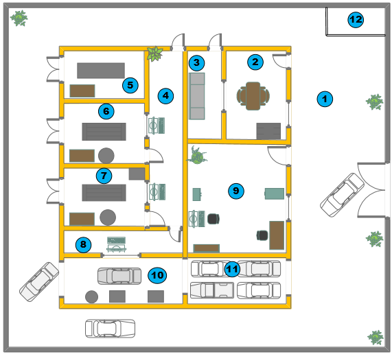
Figure 1 test lab's layout
|
1. Outdoor space 2. Cell services and equipment support 3. Instrument store 4. Engine test cells control room 5. Built and pre-rig 6. Diesel engine test cell |
7. Gasoline engine test cell 8. Chassis test cell control room 9. Office space 10. Chassis cest cell 11. Soak room 12. Fuel storage section (underground) |
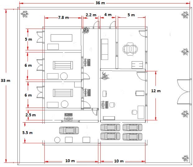
Figure 2 test lab's dimensions
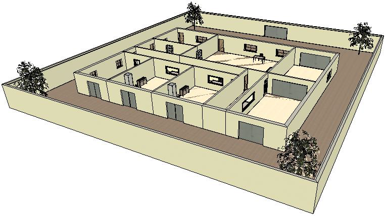
Figure 3 test lab's 3D view
Second step: instruments and equipment
The test cell required equipment and facilities are divided into four main sections as follows:
- test stand
- basic emission measurements
- supplementary cell equipments and media conditioning
- advanced emission measurement equipments
Since the main running test of the cell is considered to be the exhaust emission ones, so the advanced emission measurement equipments are considered too.
Third step: Test cell installation facilities
According to the selected engine and the cell equipments, the installation facilities have been designed and determined. The main ones are as follows:
- Air conditioning system
- Water cooling system
- Fuel storage
- Altitude conditioning system
- Firefighting alarms and equipments
- Electrical facilities
- Earth well considering
- Air compressing facility

ASA specialises in designing, installing and maintaining Automotive engine test cells. We can provide demonstrated evidence to design your new state-of-the-art engine test facility or upgrade your existing facility.
Our services include:
- Development of original specifications with the customer
- Detailed design of the test cell, data acquisition and analysis
- Consultment and supplying of the specific test cell instruments
- Fuel storage and supply tanker
- Safety systems
- Engine and facility control software
- Full operating publications
- Training solutions

An engine, powertrain or chassis (vehicle) test facility is a complex of machinery, instrumentation, and support services, housed in a building adapted or built for its purpose. For such a facility to function correctly and cost-effectively, its many parts must be matched to each other while meeting the operational requirements of the user and being compliant with relevant regulations.
Test Cell Structure
The engine and powertrain test cell structure has always been considered as a hazard containment box. Any test cell built today may be considered as “machinery” under the broad definition contained in the Machinery Directive 2006/42/EC. In this sense the cell doors are essentially now the guard for the machine. Any internal guards, such as those for the drive shaft, are essentially supplementary, i.e. additional protection to personnel when controlled access to the test cell is required and the controller is in a “reduced speed mode”. This role of the test cell as a complex programmable machine has to be kept in mind when considering all aspects of test cell design and its location within its immediate environment. The interconnected areas to be considered are:
- The engine or powertrain test cell (the hazard containment space)
- The control room (whose role may differ widely between types of users and must be defined)
- The space required for cell services and support equipment
- The support workshop, UUT rig and de-rig areas
- The storage area required for rig items and consumables
- Office space for staff directly involved with the test cell(s).


Test Cell Instruments
Engine, powertrain, and vehicle developers now need to measure improvements in performance that are frequently so small as to be in the noise band of their instrumentation. The common product of all these cells is data, which will be used to identify, modify, homologate, or develop performance criteria of all or part of the unit under test. All post-test work will rely on the relevance and veracity of the test data; the quality audit trail starts in the test cell. This level of measurement requires that every device in the measurement chain is integrated with each other and within the total facility, such that their performance and the data they produce is not compromised by the environment in which they operate, or services to which they are connected. So supplying the instruments of a modern powertrain test facility, requires the coordination of a wide range of specialized engineering skills which many technical managers have found it to be an unexpectedly wide-ranging complex project.

Test Cell Installation Facilities
When deciding to build an engine dynamometer test cell, you must consider many things. A dynamometer should be installed in a facility with proper lighting and electrical outlets and include a water supply, fuel supply, ventilation, exhaust extraction, and fire control system. These are known as the test cell facilities.
The dynamometer, engine and some of the instruments require a constant supply of cool water from an open or closed recirculating water system. Either type of system will suffice as long as the minimum flow requirements are met. Even though a closed water system initially costs substantially more than only using a local water supply source and draining it into the sewer system (or into the open field next door), the savings in the water bill over several years could pay for the difference.
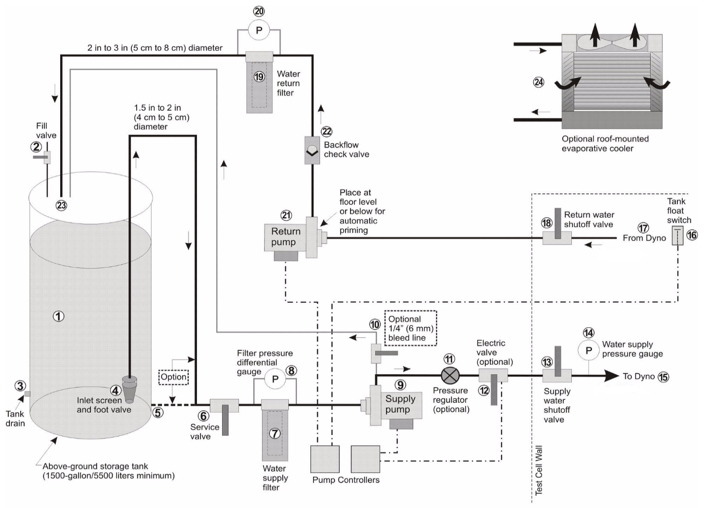
A sample cooling water system
Fuel must be readily available to supply the engine and last until all testing is completed. Because of the hazards involved with storing flammable liquids, you must carefully consider how to handle the storage and use of flammable fuels.
Proper airflow through the test cell is critical for engine cooling and room ventilation. Having a larger test cell than needed may make it difficult to control the airflow through the cell, plus the cost increases for expanded wall and floor areas as well as larger air-handling equipment.
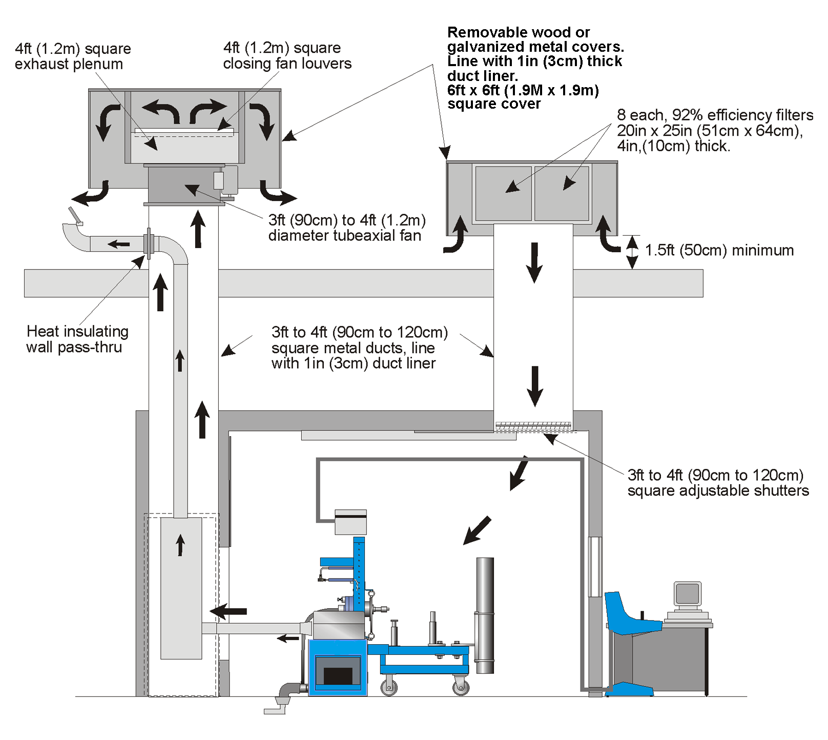
A sample ventilation system